Figure 1-1 shows the structure of the microprocessor-based personel computer system. This block diagram also applies to any computer system, from the early mainframe computers to the latest microprocessor-based systems.
Figure 1-2: The memory map of PC.
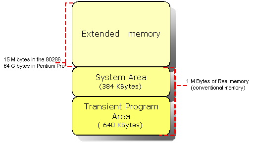
The memory system is divided into three parts ; transient program area (TPA), system area and extended memory system. The type of computer determines whether an extended memory system exists. If the computer is based upon an older 8086 or 8088, the TPA and system area exists, but there is no extended memory area. The TPA consists of 640 KB of memory where system area exists in 384 KB. That makes 1024 KB of memory or 1 M byte of memory which is refered as real or conventional memory. ( This is because each Intel microprocessor is designed to function in this area by using its real mode of operation.)
Figure 1-2 shows block diagram of a memory system.
The transient program area (TPA) holds the DOS operating system and other programs that control the computer. The TPA also stores any currently active or inactive DOS application programs.
BIOS ;( Basic I/O System ) The system BIOS is a colection of programs stored in either a read-only memory (ROM) or flash-memory that operates many of the I/O devices connected to computer system.
Flash-memory is an EEPROM (electrically erasable read-only memory) that is erased in the system electrically, while the ROM is a device that must be programmed in a special machine called EPROM programmer for an EPROM ( erasable / programmable read-only memory ) or at the factory when ROM is fabricated.
DOS ;( Disk Operating System ) Controls the way that the disk memory is organized and controlled, as well as the function and control of the some of the I/O devices connected to the system.
Figure 1-3 shows the TPA (transient program area) of memory system.
The interrupt vectors access various features of the DOS and BIOS, and applications.
The system BIOS communications area and DOS communications area contain transient data used by programs to access I/O devices and the internal features of the computer system. These are stored in the TPA so that they can be changed as the system operates. (Note that TPA contains read/write (RAM) memory ).
The IO.sys is a program that loads into the TPA from the disk whenever an MSDOS system is started. The io.sys contains programs that allow DOS to use the keyboard, video display, printer, and other I/O devices often found in the computer system. The io.sys program links DOS to the programs stored on the system BIOS ROM.
The MSDOS program area occupies twice. One area is 16 bytes in length and is located at the top of the TPA, and the other is much larger and is located near the bottom of the TPA. The DOS program controls the operation of the computer system. The size of the DOS area depends on the version of DOS installed in the computer and how it is installed. If DOS is installed in high memory with HIMEM.SYS driver, most of the TPA is free to hold application programs.
The size of the driver area and number of drivers change from one computer to another. Drivers are programs that control installable I/O devices such as a mouse, disk cache, scanner, CD-ROM memory, DVD, or installable devices,as well as programs. The driver area varies in size and contains different numbers and types of drivers.
The COMMAND.com program (command processor) controls the operation of the computer from the keyboard when operated in the DOS mode. The command.com program processes the DOS commands as they are typed from the keyboard.
The free TPA area holds DOS application programs as they are executed. TPA also holds TSR (terminate and stay resident) programs that remain in memory in an active state until activated by a hot-key sequence or another event such as an interrupt.
The system area contains programs on either a read-only memory (ROM) or flash memory
(EEPROM), and areas of read/write (RAM) memory for data storage. Figure 1-4 shows the system area of a typical computer system.
The size and amount ofmemory used in video RAM area depends on the video display adapter attached to the system, such as CGA, EGA, or one of newer forms of VGA. Generally the video RAM located in first 64 KB memory stores graphical or bit-mapped data, and the second 64 KB memory stores text data. Note that some newer video cards relocate the memory to wider, higher areas in the memory system for use under Windows operaring system.
The video BIOS ROM located on a ROM or flash memory (EEPROM), contains programs that control the DOS video display.
Hard disk conroller ROM : If a hard disk memory is attached to the computer, the interface card must contain a ROM and a disk BIOS. This ROM holds low level format software. The size , location, and presence of the ROM depend on the type of hard disk adapter attached to the computer. Note that most IDE drives do not have this ROM, but many SCSI disk interfaces do contain ROM.
The free area is used for the expanded memory system in a PC system, or for the upper memory system in an AT system. Its use depends on the system and its configuration. The expanded memory system allow a 64 K-byte page frame of memory to be used by application programs. This 64 K-byte page frame is used to expand memory system by switching in pages of memory from EMS into this range of memory addresses. Note that the information is addressed şn the page frame as 16 K-byte sized pages of data that are swapped with pages from EMS. Figure 1-5 shows the expanded memory system. Note that expanded memory is slow because the change to a new 16 K-byte memory page requires action by the driver. Also note that expanded memory was designed to expand memory system early 8086/8088-based computer systems. In most cases, except for some DOS-based games that use the sound card, expanded memory should be avoided in 80386-Pentium IV- based systems.
Next memory location contain casette BASIC language on ROM found in early IBM personal computer systems. This area is often open or free in newer computer systems. In newer systems, we often back-fill this area with extra RAM for use by DOS programs, called upper memory. Each upper memory block is 4 K bytes in length.
The system BIOS ROM controls the operation of the basic I/O devices connected to the computer system. It does not control the operation of the video system, which has its own BIOS ROM. The first part of the system BIOS often contains programs that set up the computer. Second part contains procedures that control the basic I/O system. Once the system is set up, upper memory blocks are available is EMM386.EXE is installed.
The I/O (input/output) space is a computer system extends from I/O port 0000H (0) to port FFFFH (65535). This port addressing system is similar to a memory address, except that instead of addressing memory, it addresses an I/O device.
The I/O devices allow the microprocessor to communicate between itself and outside world. The I/O space allows computer to access up to 64 K (65535) different 8-bit I/O devices. A great number of these locations are available for expansion in newer computer systems. Figure 1-6 shows the I/O map found in many personal computers.
The I/O area contains two major sections. The area below I/O location 0400H is considered reserved for system devices. The remaining area is available I/O space for expansion on newer systems that extends from I/O port 0400H (1024) through FFFFH. Some of the mainboards in newer computer systems also use other addresses above 400H. Generally, I/O addresses between 0000H and 00FFH (255) address components on the mainboard of the computer, while addresses between 0100H and 03FFH (1023) addresses devices located on plug-in cards. Note that the limitation of I/O addresses between 0000H and 03FFH comes from the original PC standart.
The Microprocessor is the heart of the microprocessor-based computer system. The Microprocessor (CPU) is the controlling element of in a computer system. The microprocessor controls memory and I/O through a series of connection called buses. The buses select an I/O or memory device, transfer data between an I/O device or memory and the microprocessor, and control the I/O and memory system. Memory and I/O are controlled through instructions that are stored in the memory and executed by the microprocessor.
The microprocessor performs three main tasks for the computer system ;
1. data transfer between itself and the memory or I/O systems,
2. simple arithmetic and logic operations, and
3. program flow via simple decisions.
 These are simple tasks but the microprocessor performs any series of operations or tasks through them. Table 1-1 shows the arithmetic and logic operations executed by Intel family of microprocessors. Table 1-2 shows the decisions found in microprocessors. Beginning with the 80486, the microprocessor contained a numeric coprocessor that allowed it to perform complex arithmetic using floating-point arithmetic.
A bus is set of common connections that carry the same type of information. A bus is a common group of wires that interconnect the sections of a computer system. The buses transfer address, data, and control information between the microprocessor and its memory and I/O systems. In the microprocessor-based computer system three buses exist for this transfer of information ;
1. Address,
2. Data, and
3. Control.
Figure 1-7 shows how these buses interconnect various system components.
The address bus requests a memory location from the memory or an I/O location from the I/O devices. If I/O is addressed, the address bus contains a 16-bit I/O address from 0000H through FFFFH. The 16-bit I/O address, or port number, selects one of 64K different I/O devices. If memory is addressed, the address bus contains a memory address, which varies in width with the different versions of the microprocessor.
The data bus transfers information between the microprocessor and its memory and I/O address space. Data transfers vary in size, from 8-bits wide to 64 bits wide in various members of microprocessors. The advantage of wider data bus is speed in applications that use wide data. If a 32-bit number stored in the memory, it takes four transfer operations for a 8-bit data bus to complete transfer. A 32-bit wide data bus does the same job with one transfer.
The control bus contains lines that select the memory or I/O and cause tham to perform a read or write operation. There are four control bus connections ;
1.  ; memory read control
2.  ; memroy write control
3.  ; I/O read control
4.  ; I/O write control
The microprocessor reads the contents of a memory location by sending the memory address through the address bus. Next it sends the memory read control signal () to cause memory to read data. Finally, the data read from the memory are passed to the microprocessor through the data bus. Whenever a memory write, I/O write, or I/O read occurs, the same sequence ensues, except that different control signals are issued and the data flow out of the microprocessor through its data bus for a write operation.
Examples of buses are as follows ;
Address Bus ; contains 20 or more connections, conveys the memory address to the memory.
PCI Bus ( Peripheral Component Interconnect ) ; Used almost in all Pentium II systems.
VESA Local Bus (VL Bus) ; Interfaces disk and video to the microprocessor at the local bus level, which allows 32-bit interfaces to function at the same clocking speed as the microprocessor.
USB Bus ( Universal Serial Bus ) ;Intended to connect peripheral devices such as keyboards, a mouse, modems, and sound cards to the microprocessor through a serial data path and a twisted pair of wires. The main idea is to reduce system cost by reducing the number of wires.
AGP Bus ( Advanced Graphics Port ) ;Transfers data between the video card and the microprocessor at higher speeds, with a 64-bit data path, than were possible through any other bus or connection. >